T HE L EVER
In its most basic form, the lever consists of a rigid bar supported at one point, known as the fulcrum. One of the simplest examples of a lever is a crowbar, which one might use to move a heavy object, such as a rock. In this instance, the fulcrum could be the ground, though a more rigid "artificial" fulcrum (such as a brick) would probably be more effective.
As the operator of the crowbar pushes down on its long shaft, this constitutes an input of force, variously termed applied force, effort force, or merely effort. Newton's third law of motion shows that there is no such thing as an unpaired force in the universe: every input of force in one area will yield an output somewhere else. In this case, the output is manifested by dislodging the stone—that is, the output force, resistance force, or load.
Use of the lever gives the operator much greater lifting force than that available to a person who tried to lift with only the strength of his or her own body. Like all machines, the lever links input to output, harnessing effort to yield beneficial results—in this case, by translating the input effort into the output effort of a dislodged stone. Note, however, the statement at the beginning of this paragraph: proper use of a lever actually gives a person much greater force than he or she would possess unaided. How can this be?
There is a close relationship between the behavior of the lever and the concept of torque, as, for example, the use of a wrench to remove a lug nut. A wrench, in fact, is a sort of lever (Class I—a distinction that will be explored below.) In any object experiencing torque, the distance from the pivot point (the lug nut, in this case), to the area where force is being applied is called the moment arm. On the wrench, this is the distance from the lug nut to the place where the operator is pushing on the wrench handle. Torque is the product of force multiplied by moment arm, and the greater the torque, the greater the tendency of the object to be put into rotation. As with machines in general, the greater the input, the greater the output.
The fact that torque is the product of force and moment arm means that if one cannot increase force, it is still possible to gain greater torque by increasing the moment arm. This is the reason why, when one tries and fails to disengage a stubborn lug nut, it is a good idea to get a longer wrench. Likewise with a lever, greater leverage can be gained without applying more force: all one needs is a longer lever arm.
As one might suspect, the lever arm is the distance from the force input to the fulcrum, or from the fulcrum to the force output. If a carpenter is using a nail-puller on the head of a hammer to extract a nail from a board, the lever arm of force input would be from the carpenter's hand gripping the hammer handle to the place where the hammerhead rests against the board. The lever arm of force output would be from the hammerhead to the end of the nail-puller.
With a lever, the input force (that of the carpenter's hand pulling back on the hammer handle) multiplied by the input lever arm is always equal to the output force (that of the nail-puller pulling up the nail) multiplied by the output lever arm. The relationship between input and output force and lever arm then makes it possible to determine a formula for the lever's mechanical advantage.
Since F in L in = F out L out (where F = force and L = lever arm), it is possible to set up an equation for a lever's mechanical advantage. Once again, mechanical advantage is always F out / F in , but with a lever, it is also L in / L out . Hence, the mechanical advantage of a lever is always the same as the inverse ratio of the lever arm. If the input arm is 5 units long and the output arm is 1 unit long, the mechanical advantage will be 5, but if the positions are reversed, it will be 0.2.
CLASSES OF LEVERS.
Levers are divided into three classes, depending on the relative positions of the input lever arm, the fulcrum, and the output arm or load. In a Class I lever, such as the crowbar and the wrench, the fulcrum is between the input arm and the output arm. By contrast, a Class II lever, for example, a wheelbarrow, places the output force (the load carried in the barrow itself) between the input force (the action of the operator lifting the handles) and the fulcrum, which in this case is the wheel.
Finally, there is the Class III lever, which is the reverse of a Class II. Here, the input force is between the output force and the fulcrum. The human arm itself is an example of a Class III lever: if one grasps a weight in one's hand, one's bent elbow is the fulcrum, the arm raising the weight is the input force, and the weight held in the hand—now rising—is the output force. The Class III lever has a mechanical advantage of less than 1, but what it loses in force output in gains in range of motion.
The world abounds with levers. Among the Class I varieties in common use are a nail puller on a hammerhead, described earlier, as well as postal scales and pliers. A handcart, though it might seem at first like a wheelbarrow, is actually a Class I lever, because the wheel or fulcrum is between the input effort—the force of a person's hands gripping the handles—and the output, which is the lifting of the load in the handcart itself. Scissors constitute an interesting type of Class I lever, because the force of the output (the cutting blades) is reduced in order to create a greater lever arm for the input, in this case the handles gripped when cutting.
A handheld bottle opener provides an excellent illustration of a Class II lever. Here the fulcrum is on the far end of the opener, away from the operator: the top end of the opener ring, which rests atop the bottle cap. The cap itself is the load, and one provides input force by pulling up on the opener handle, thus prying the cap from the bottle with the lower end of the opener ring. Nail clippers represent a type of combination lever: the handle that one operates is a Class II, while the cutting blades are a Class III.
Whereas Class II levers maximize force at the expense of range of motion, Class III levers operate in exactly the opposite fashion. When using a fishing rod to catch a fish, the fisherman's left hand (assuming he is
right-handed) constitutes the fulcrum as it holds the rod just below the reel assembly. The right hand supplies the effort, jerking upward, while the fish is the load. The purpose here is not to raise a heavy object (one reason why a fishing rod may break if one catches too large a fish) but rather to use the increased lever arm for one's advantage in catching an object at some distance. Similarly, a hammer, which constitutes a Class III lever, with the operator's wrist as fulcrum, magnifies the motion of the operator's hand with a hammerhead that cuts a much wider arc.
Many machines that arose in the Industrial Age are a combination of many levers—that is, a compound lever. In a manual
typewriter or piano, for instance, each key is a complex assembly of levers designed for a given task. An automobile, too, uses multiple levers—most notably, a special variety known as the wheel and axle.
THE WHEEL AND AXLE.
A wheel is a variation on a Class I lever, but it represents such a stunning technological advancement that it deserves to be considered on its own. When driving a car, the driver places input force on the rim of the steering wheel, whose fulcrum is the center of the wheel. The output force is translated along the steering column to the driveshaft.
The combination of wheel and axle overcomes one factor that tends to limit the effectiveness of most levers, regardless of class: limited range of motion. An axle is really a type of wheel, though it has a smaller radius, which means that the output lever arm is correspondingly smaller. Given what was already said about the equation for mechanical advantage in a lever, this presents a very fortunate circumstance.
When a wheel turns, it has a relatively large lever arm (the rim), that turns a relatively small lever arm, the axle. Because the product of input force and input lever arm must equal output force multiplied by output lever arm, this means that the output force will be higher than the input force. Therefore, the larger the wheel in proportion to the axle, the greater the mechanical advantage.
It is for this reason that large vehicles without power steering often have very large steering wheels, which have a larger range of motion and, thus, a greater torque on the axle—that is, the steering column. Some common examples of the wheel-and-axle principle in operation today include a doorknob and a screwdriver; however, long before the development of the wheel and axle, there were wheels alone.
There is nothing obvious about the wheel, and in fact, it is not nearly as old an invention as most people think. Until the last few centuries, most peoples in sub-Saharan Africa, remote parts of central and northern Asia, the Americas, and the Pacific Islands remained unaware of it. This did not necessarily make them "primitive": even the Egyptians who built the Great Pyramid of Cheops in about 2550
B.C. had no concept of the wheel.
What the Egyptians did have, however, were rollers—-most often logs, onto which a heavy object was hoisted using a lever. From rollers developed the idea of a sledge, a sled-like device for sliding large loads atop a set of rollers. A sledge appears in a Sumerian illustration from about 3500
B.C. , the oldest known representation of a wheel-like object.
The transformation from the roller-and-sledge assembly to wheeled vehicles is not as easy as it might seem, and historians still disagree as to the connection. Whatever the case, it appears that the first true wheels originated in Sumer (now part of Iraq) in about 3500
B.C. These were tripartite wheels, made by attaching three pieces of wood and then cutting out a circle. This made a much more durable wheel than a sawed-off log, and also overcame the fact that few trees are perfectly round.
During the early period of wheeled transportation, from 3500 to 2000
B.C. , donkeys and oxen rather than horses provided the power, in part because wheeled vehicles were not yet made for the speeds that horses could achieve. Hence, it was a watershed event when wheelmakers began fashioning axles as machines separate from the wheel. Formerly, axles and wheels were made up of a single unit; separating them made carts much more stable, especially when making turns—and, as noted earlier, greatly increased the mechanical advantage of the wheels themselves.
Transportation entered a new phase in about 2000
B.C. , when improvements in technology made possible the development of spoked wheels. By heat-treating wood, it became possible to bend the material slightly, and to attach spokes between the rim and hub of the wheel. When the wood cooled, the tension created a much stronger wheel—capable of carrying heavier loads faster and over greater distances.
In China during the first century
B.C. , a new type of wheeled vehicle—identified earlier as a Class II lever—was born in the form of the wheelbarrow, or "wooden ox." The wheelbarrow, whose invention the Chinese attributed to a semi-legendary figure named Ko Yu, was of such value to the imperial army for moving arms and military equipment that China's rulers kept its design secret for centuries.
In Europe, around the same time, chariots were dying out, and it was a long time before the technology of wheeled transport improved. The first real innovation came during the 1500s, with the development of the horsedrawn coach. By 1640, a German family was running a regular stagecoach service, and, in 1667, a new, light, two-wheeled carriage called a
cabriolet made its first appearance. Later centuries, of course, saw the development of increasingly more sophisticated varieties of wheeled vehicles powered in turn by human effort (the bicycle), steam (the locomotive), and finally, the internal combustion engine (the automobile.)
But the wheel was never just a machine for transport: long before the first wheeled carts came into existence, potters had been using wheels that rotated in place to fashion perfectly round objects, and in later centuries, wheels gained many new applications. By 500
B.C. , farmers in Greece and other parts of the Mediterranean world were using rotary mills powered by donkeys. These could grind grain much faster than a person working with a hand-powered grindstone could hope to do, and in time, the Greeks found a means of powering their mills with a force more useful than donkeys: water.
The first waterwheels, turned by human or animal power, included a series of buckets along the rim that made it possible to raise water from the river below and disperse it to other points. By about 70
B.C. , however, Roman engineers recognized that they could use the power of water itself to turn wheels and grind grain. Thus, the water-wheel became one of the first two rotor mechanisms in which an inanimate source (as opposed to the effort of humans or animals) created power to spin a shaft.
In this way, the waterwheel was a prototype for the engine developed many centuries later. Indeed, in the first century
A.D. , Hero of Alexandria—who discovered the concept of steam power some 1,700 years before anyone took up the idea and put it to use—proposed what has been considered a prototype for the turbine engine. However, for a variety of complex reasons, the ancient world was simply not ready for the technological leap portended by such an invention; and so, in terms of significant progress in the development of machines, Europe was asleep for more than a millennium.
The other significant form of wheel powered by an "inanimate" source was the
windmill, first mentioned in 85
B.C. by Antipater of Thessalonica, who commented on a windmill he saw in northern Greece. In this early version of the windmill, the paddle wheel moved on a horizontal plane. However, the windmill did not take hold in Europe during ancient times, and, in fact, its true origins lie further east, and it did not become widespread until much later.
In the seventh century
A.D. , windmills began to appear in the region of modern Iran and Afghanistan, and the concept spread to the Arab world. Europeans in the Near East during the Crusades (1095-1291) observed the windmill, and brought the idea back to Europe with them. By the twelfth century Europeans had developed the more familiar vertical mill.
Finally, there was a special variety of wheel that made its appearance as early as 500
B.C. : the toothed gearwheel. By 300
B.C. , it was in use throughout Egypt, and by about 270
B.C. , Ctesibius of Alexandria (fl. c. 270-250
B.C. ) had applied the gear in devising a constant-flow water clock called a clepsydra.
Some 2,100 years after Ctesibius, toothed gears became a critical component of industrialization. The most common type is a spur gear, in which the teeth of the wheel are parallel to the axis of rotation. Helical gears, by contrast, have curved teeth in a spiral pattern at an angle to their rotational axes. This means that several teeth of one gearwheel are always in contact with several teeth of the adjacent wheel, thus providing greater torque.
In bevel gears, the teeth are straight, as with a spur gear, but they slope at a 45°-angle relative to their axes so that two gearwheels can fit together at up to 90°-angles to one another without a change in speed. Finally, planetary gears are made such that one or more smaller gearwheels can fit within a larger gearwheel, which has teeth cut on the inside rather than the outside.
Similar in concept to the gearwheel is the V belt drive, which consists of two wheels side by side, joined with a belt. Each of the wheels has grooves cut in it for holding the belt, making this a modification of the pulley, and the grooves provide much greater gripping power for holding the belt in place. One common example of a V belt drive, combined with gearwheels, is a bicycle chain assembly.
PULLEYS.
A pulley is essentially a grooved wheel on an axle attached to a frame, which in turn is attached to some form of rigid support such as a ceiling. A rope runs along the grooves of the pulley, and one end is attached to a load while the other is controlled by the operator.
In several instances, it has been noted that a machine may provide increased range of motion or position rather than power. So, this simplest kind of pulley, known as a single or fixed pulley, only offers the advantage of direction rather than improved force. When using Venetian blinds, there is no increase in force; the advantage of the machine is simply that it allows one to move objects upward and downward. Thus, the theoretical mechanical advantage of a fixed pulley is 1 (or almost certainly less under actual conditions, where
friction is a factor).
Here it is appropriate to return to
Archimedes, whose advancements in the understanding of levers translated to improvements in pulleys. In the case of the lever, it was Archimedes who first recognized that the longer the effort arm, the less effort one had to apply in raising the load. Likewise, with pulleys and related devices—cranes and winches—he explained and improved the way these machines worked.
The first
crane device dates to about 1000
B.C. , but evidence from pictures suggests that pulleys may have been in use as early as seven thousand years before. Several centuries before Archimedes's time, the Greeks were using compound pulleys that contained several wheels and thus provided the operator with much greater mechanical advantage than a fixed pulley. Archimedes, who was also the first to recognize the relationship between pulleys and levers, created the first fully realized block-and-tackle system using compound pulleys and cranes. In the late modern era, compound pulley systems were used in applications such as elevators and escalators.
A compound pulley consists of two or more wheels, with at least one attached to the support while the other wheel or wheels lift the load. A rope runs from the support pulley down to the load-bearing wheel, wraps around that pulley and comes back up to a fixed attachment on the upper pulley. Whereas the upper pulley is fixed, the load-bearing pulley is free to move, and raises the load as the rope is pulled below.
The simplest kind of compound pulley, with just two wheels, has a mechanical advantage of 2. On a theoretical level, at least, it is possible to calculate the mechanical advantage of a compound pulley with more wheels: the number is equal to the segments of rope between the lower pulleys and the upper, or support pulley. In reality, however, friction, which is high as ropes rub against the pulley wheels, takes its toll. Thus mechanical advantage is never as great as it might be.
A block-and-tackle, like a compound pulley, uses just one rope with a number of pulley wheels. In a block-and-tackle, however, the wheels are arranged along two axles, each of which includes multiple pulley wheels that are free to rotate along the axle. The upper row is attached to the support, and the lower row to the load. The rope connects them all, running from the first pulley in the upper set to the first in the lower set, then to the second in the upper set, and so on. In theory, at least, the mechanical advantage of a block-and-tackle is equal to the number of wheels used, which must be an even number—but again, friction diminishes the theoretical mechanical advantage.
T HE I NCLINED P LANE
To the contemporary mind, it is difficult enough to think of a lever as a "machine"—but levers at least have more than one part, unlike an inclined plane. The latter, by contrast, is exactly what it seems to be: a ramp. Yet it was just such a ramp structure, as noted earlier, that probably enabled the Egyptians to build the pyramids—a feat of engineering so stunning that even today, some people refuse to believe that the ancient Egyptians could have achieved it on their own.
Surely, as anti-scientific proponents of various fantastic theories often insist, the building of the pyramids could only have been done with machines provided by super-intelligent, extraterrestrial beings. Even in ancient times, the Greek historian Herodotus (c. 484-c. 424 B.C. ) speculated that the Egyptians must have used huge cranes that had long since disappeared.
These bizarre guesses concerning the technology for raising the pyramid's giant blocks serve to highlight the brilliance of a gloriously simple machine that, in essence, doubles force. If one needs to move a certain weight to a certain height, there are two options. One can either raise the weight straight upward, expending an enormous amount of effort, even with a pulley system; or one can raise the weight gradually along an inclined plane. The inclined plane is a much wiser choice, because it requires half the effort.
Why half? Imagine an inclined plane sloping evenly upward to the right. The plane exists in a sort of frame that is equal in both length and height to the dimensions of the plane itself. As we can easily visualize, the plane takes up exactly half of the frame, and this is true whether the slope is more than, less than, or equal to 45°. For any plane in which the slope is more than 45°, however, the mechanical advantage will be less than 1, and it is indeed hard to imagine why anyone would use such a plane unless forced to do so by limitations on their horizontal space—for example, when lifting a heavy object from a narrow canyon.
The mechanical advantage of an inclined plane is equal to the ratio between the distance over which input force is applied and the distance of output; or, more simply, the ratio of length to height. If a man is pushing a crate up a ramp 4 ft high and 8 ft long (1.22 m by 2.44 m), 8 ft is the input distance and 4 ft the output distance; hence, the mechanical advantage is 2. If the ramp length were doubled to 16 ft (4.88 m), the mechanical advantage would likewise double to 4, and so on.
The concept of work, in terms of physics, has specific properties that are a subject unto themselves; however, it is important here only to recognize that work is the product of force (that is, effort) multiplied by distance. This means that if one increases the distance, a much smaller quantity of force is needed to achieve the same amount of work.
On an everyday level, it is easy to see this in action. Walking or running up a gentle hill, obviously, is easier than going up a steep hill. Therefore, if one's primary purpose is to conserve effort, it is best to choose the gentler hill. On the other hand, one may wish to minimize distance—or, if moving for the purpose of exercise, to maximize force input to burn calories. In either case, the steeper hill would be the better option.
WEDGES.
The type of inclined plane discussed thus far is a ramp, but there are a number of much smaller varieties of inclined plane at work in the everyday world. A knife is an excellent example of one of the most common types, a wedge. Again, the mechanical advantage of a wedge is the ratio of length to height, which, in the knife, would be the depth of the blade compared to its cross-sectional width. Due to the ways in which wedges are used, however, friction plays a much greater role, therefore greatly reducing the theoretical mechanical advantage.
Other types of wedges may be used with a lever, as a form of fulcrum for raising objects. Or, a wedge may be placed under objects to stabilize them, as for instance, when a person puts a folded matchbook under the leg of a restaurant table to stop it from wobbling. Wedges also stop other objects from moving: a triangular piece of wood under a door will keep it from closing, and a more substantial wedge under the front wheels of a car will stop it from rolling forward.
Variations of the wedge are everywhere. Consider all the types of cutting or chipping devices that exist: scissors, chisels, ice picks, axes, splitting wedges (used with a mallet to split a log down the center), saws, plows, electric razors, etc. Then there are devices that use a complex assembly of wedges working together. The part of a key used to open a lock is really just a row of wedges for moving the pins inside the lock to the proper position for opening the door. Similarly, each tooth in a zipper is a tiny wedge that fits tightly with the adjacent teeth.
SCREWS.
As the wheel is, without a doubt, the greatest conceptual variation on the lever, so the screw may be identified as a particularly cunning adaptation of an inclined plane. The uses of screws today are many and obvious, but as with wheels and axles, these machines have more applications than are commonly recognized. Not only are there screws for holding things together, but there are screws such as those on vises, clamps, or monkey wrenches for applying force to objects.
A screw is an inclined plane in the shape of a helix, wrapped around an axis or cylinder. In order to determine its mechanical advantage, one must first find the pitch, which is the distance
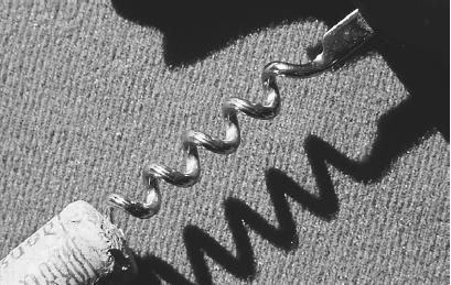
A
SCREW ,
LIKE THIS CORKSCREW USED TO OPEN A BOTTLE OF WINE ,
IS AN INCLINED PLANE IN THE SHAPE OF A HELIX ,
WRAPPED AROUND AN AXIS OR CYLINDER . (
Ecoscene/Corbis
.
Reproduced by permission.)
between adjacent threads. The other variable is lever arm, which with a screwdriver is the radius, or on a wrench, the length from the crescent or clamp to the area of applied force. Obviously, the lever arm is much greater for a wrench, which explains why a wrench is sometimes preferable to a screwdriver, when removing a highly resistant material screw or bolt.
When one rotates a screw of a given pitch, the applied force describes a circle whose area may be calculated as 2π
L, where
L is the lever arm. This figure, when divided by the pitch, is the same as the ratio between the distance of force input to force output. Either number is equal to the mechanical advantage for a screw. As suggested earlier, that mechanical advantage is usually low, because force input (screwing in the screw) takes place in a much greater range of motion than force output (the screw working its way into the surface). But this is exactly what the screw is designed to do, and what it lacks in mechanical advantage, it more than makes up in its holding power.
As with the lever and pulley, Archimedes did not invent the screw, but he did greatly improve human understanding of it. Specifically, he developed a
mathematical formula for a simple spiral, and translated this into the highly practical Archimedes screw, a device for lifting water. The invention consists of a metal pipe in a corkscrew shape, which draws water upward as it revolves. It proved particularly useful for lifting water that had seeped into the lower parts of a ship, and in many countries today, it remains in use as a simple pump for drawing water out of the ground.
Some historians maintain that Archimedes did not invent the screw-type pump, but rather saw an example of it in Egypt. In any case, he clearly developed a practical version of the device, and it soon gained application throughout the ancient world. Archaeologists discovered a screw-driven olive press in the ruins of Pompeii, destroyed by the eruption of
Mt. Vesuvius in
A.D. 79, and Hero of Alexandria later mentioned the use of a screw-type machine in his
Mechanica.
Yet, Archimedes is the figure most widely associated with the development of this wondrous device. Hence, in 1837, when the Swedish-American engineer John Ericsson (1803-1899) demonstrated the use of a screw-driven ship's propeller, he did so on a craft he named the Archimedes.
From screws planted in wood to screws that drive ships at sea, the device is everywhere in modern life. Faucets, corkscrews, drills, and meat grinders are obvious examples. Though many types of jacks used for lifting an automobile or a house are levers, others are screw assemblies on which one rotates the handle along a horizontal axis. In fact, the jack is a particularly interesting device. Versions of the jack represent all three types of simple machine: lever, inclined plane, and hydraulic press.
T HE H YDRAULIC P RESS
As noted earlier, the hydraulic press came into existence much, much later than the lever or inclined plane, and its birth can be seen within the context of a larger movement toward the use of water power, including steam. A little more than a quarter-century after Pascal created the theoretical framework for hydraulic power, his countryman
Denis Papin (1647-1712) introduced the steam digester, a prototype for the pressure cooker. In 1687, Papin published a work describing a machine in which steam operated a piston—an early model for the steam engine.
Papin's concept, which was on the absolute cutting edge of technological development at that time, utilized not only steam power but also the very hydraulic concept that Pascal had identified a few decades earlier. Indeed, the assembly of pistons and cylinders that forms the central component of the internal-combustion engine reflects this hydraulic rule, discovered by Pascal in 1653. It was then that he formulated what is known as Pascal's principle: that the external pressure applied on a fluid is transmitted uniformly throughout the entire body of that fluid.
Inside a piston and cylinder assembly, one of the most basic varieties of hydraulic press, the pressure is equal to the ratio of force to the horizontal area of pressure. A simple hydraulic press of the variety that might be used to raise a car in an auto shop typically consists of two large cylinders side by side, connected at the bottom by a channel in which valves control flow. When one applies force over a given area of input—that is, by pressing down on one cylinder—this yields a uniform pressure that causes output in the second cylinder.
Once again, mechanical advantage is equal to the ratio of force output to force input, and for a hydraulic press, this can also be measured as the ratio of area output to area input. Just as there is an inverse relationship between lever arm and force in a lever, and between length and height in an inclined plane, so there is such a relationship between horizontal area and force in a hydraulic pump. Consequently, in order to increase force, one should minimize area.
However, there is another factor to consider: height. The mechanical advantage of a hydraulic pump is equal to the vertical distance to which the input force is applied, divided by that of the output force. Hence, the greater the height of the input cylinder compared to the output cylinder, the greater the mechanical advantage. And since these three factors—height, area, and force—work together, it is possible to increase the lifting force and area by minimizing the height.
Consider once again the auto-shop car jack. Typically, the input cylinder will be relatively tall and thin, and the output cylinder short and squat. Because the height of the input cylinder is large, the area of input will be relatively small, as will the force of input. But according to Pascal's principle, whatever the force applied on the input, the pressure will be the same on the output. At the output end, where the car is raised, one needs a large amount of force and a relatively large lifting area. Therefore, height is minimized to increase force and area. If the output area is 10 times the size of the input area, an input force of 1 unit will produce an output force of 10 units—but in order to raise the weight by 1 unit of height, the input piston must move downward by 10 units.
This type of car jack provides a basic model of the hydraulic press in operation, but, in fact, hydraulic technology has many more applications. A hydraulic pump, whether for pumping air into a tire or water from a basement, uses very much the same principle as the hydraulic jack. So too does the hydraulic ram, used in machines ranging from bulldozers to the hydraulic lifts used by firefighters and utility workers to reach great heights.
In a hydraulic ram, however, the characteristics of the input and output cylinders are reversed from those of a car jack. The input cylinder, called the master cylinder, is short and squat, whereas the output cylinder—the slave cylinder—is tall and thin. The reason for this change is that in objects using a hydraulic ram, height is more important than force output: they are often raising people rather than cars. When the slave cylinder exerts pressure on the stabilizer ram above it (the bucket containing the firefighter, for example), it rises through a much larger range of vertical motion than that of the fluid flowing from the master cylinder.
As noted earlier, the pistons of a car engine are hydraulic pumps—specifically, reciprocating hydraulic pumps, so named because they all work together. In scientific terms, "fluid" can mean either a liquid or a gas such as air; hence, there is an entire subset of hydraulic machines that are pneumatic, or air-powered. Among these are power brakes in a car, pneumatic drills, and even hovercrafts. As with the other two varieties of simple machine, the hydraulic press is in evidence throughout virtually every nook and cranny of daily life. The pump in a toilet tank is a type of hydraulic press, as is the inner chamber of a pen. So too are aerosol cans, fire extinguishers, scuba tanks, water meters, and pressure gauges.
Read more: http://www.scienceclarified.com/everyday/Real-Life-Physics-Vol-2/Mechanical-Advantage-and-Simple-Machines-Real-life-applications.html#ixzz3Zez6HQ3L


